|
|
Replacing E04 Power End Bearings |
|
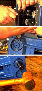
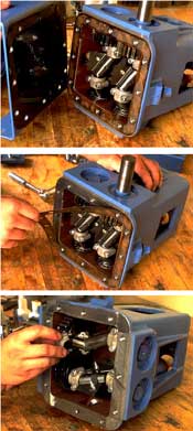
Step 1 Remove bottom drain pipe plug and drain all oil from power frame. Step 2 Disconnect suction and discharge piping, power source, and remove pump from mounting base. Step 3 Although it is not required, it is easier to remove the crankshaft if the fluid end and pistons have been removed. To remove the fluid end, follow steps 1-3 of the section titled Replacing Piston Cup Seals. Step 4 Remove the 12 (12) hex head cap screws, Step 5 Remove cap screws from the connecting rod assemblies and take out the back half of the four (4) the connecting rods. Note the orientation of the machine markings on the connecting rod and cap. Connecting rod halves are not interchangeable and must be reassembled in their original orientation and in the same cylinder. Step 6 Remove the oil slinger from the crankshaft. Step 7 Push the connecting rods and crosshead assemblies as far forward into the power frame as possible to provide clearance for the crankshaft. Step 8 Use snap ring pliers to remove the four (4) crankshaft retainer snap rings from each side of the pump. Step 9 Using a hammer and wood block (or rubber mallet on the end of the crankshaft), drive each crankshaft until one bearing on each shaft clears the power frame. Drive from the gear side of the shafts. Step 10 Remove the exposed bearings from the crankshaft using a press. Be sure to provide suitable support for the back side of the bearings during this step. Note: Never pound directly on the bearings or they may be damaged. Crankshafts with single bearing on each end may now be removed through bottom of power frame. Step 11 Carefully clean and inspect all parts. Replace worn or damaged components as necessary. Step 12 Place a single bearing on the gear side of each crankshaft and install in pump. Once the crankshaft has been placed in the proper position in the power frame the remaining bearings can be installed on the opposite end of the shaft. Step 13 Insure that timing marks on gears are aligned as shown for proper piston motion. Arrow (or dot) on one gear must be centered between two arrows (or dots) on other gear. Note area highlighted by circle in photo to right. Step 14 Place the oil seals over the ends of the crankshaft with the lip of the seals facing the inside of the power frame.
Step 15 Seat the snap rings in the grooves in the bearing housing against the oil seals and tap the crankshaft to allow a SLIGHT endplay in the crankshaft. Step 16 Reassemble the connecting rods and shell bearings around the crankshaft. The connecting rod and cap are a matched set. Be sure to properly match the connecting rods and caps back into their original position, orientation, and cylinder. Torque connecting rod bolts as shown in the Fastener Torque Requirements section. Step 17 Complete the reassembly by reversing steps 1-8. Torque mounting base cap screws as shown in the Fastener Torque Requirements section of this manual. Be sure to replace the drain plug in the mounting base. Step 18 Refill the power frame with oil and turn the shaft over several revolutions by hand. When piston cups are not installed the pump shaft should rotate freely.
|
|