|
|
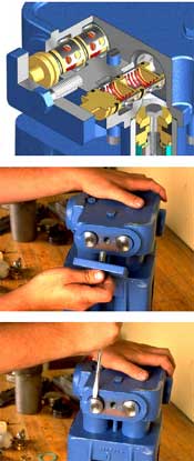
Replacing E04 Suction and Discharge Valves |
|
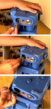
Step 1 To access the suction and discharge valves, the valve cover clamps must be removed from each side of the fluid chamber. Remove cap screw and valve cover clamp from the each side of the fluid chamber. Step 2 Insert the end of a standard screwdriver into the valve cover groove and pry each of the four the valve covers away from the fluid chamber and remove. Step 3 Remove the discharge valve disc-spring assembly and the perforated valve cage from each of the four (4) pump cylinders. Step 4 Use a finger to reach through the opening at the center of the seat and work the seat loose from the chamber. Note, the optional valve seat removal tool (FMC part number 1250638) may be used to simplify this procedure. Insert the round end of the tool into the seat and rock from side to side to loosen the seat, then use the other end of the tool to hook under the valve seat and remove. Step 5 Use the same procedure to remove the suction valve cage and valve seat, which are located directly under the discharge valve seat. Turning the valve seat on edge will help it go through the discharge valve seating area easier. Repeat for the remaining three (3) pump cylinders. Step 6 Inspect all valve components and replace as necessary. Note that even small damage or erosion to the sealing area of the valve or the o-ring can adversely affect the performance of the pump. Step 7 With the o-ring in place on each valve seat, place a few drops of light oil around the o-ring to aid in installation. Place each valve seat SQUARELY in the counter bore in the bottom of the fluid chamber. Turn the valve seat on edge to help pass through the narrow areas of the pump. Use the round end of the FMC Technologies valve tool to aid in installation of the valve seats. Step 8Place the valve cage on the valve seat and insert the disc/spring assembly inside of the cage on the valve seat. Note that the bottom of the valve disk should be installed facing the top of the valve seat. Step 9 Repeat the previous two (2) steps to install the discharge valve seat and the discharge valve cage. Step 10 Place the valve covers (with o-rings on BOTTOM groove) in place over the valve assembly. Step 11 Replace valve cover clamp and cap screw and tighten as shown in the Fastener Torque Requirements. Note: Over tightening the cap screw can damage the valve components.
|
|