|
|
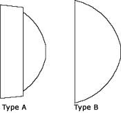
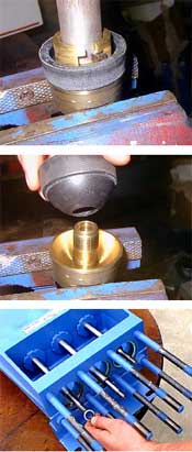
Due to their larger uninstalled diameter, Type B piston
cups on L0918 pumps (2.25” nominal bore diameter) cannot be inserted
through the fluid end without the risk of damaging the sealing surface of
the cup. L0914 pumps, or any pump with a Type A cup, are not affected and
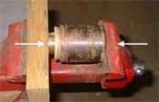
can skip directly to step 1. Type B L0918 pistons must be installed in the piston
liners using a press or vice as shown to the right. Be sure to protect
both ends of the assembly with a wood blocks, soft jaw vice, or other
suitable method to insure they are not damaged during this process. Press the piston assembly into the liners until the sealing lip has just entered the front of the liner. Use a small amount of glycerin on the ID of the liner to help lubricate the piston during installation. After the liner has been installed in the pump power frame, drive the piston assembly fully to its stop using the FMC Technologies piston tool (A5049) and a rubber mallet.
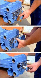
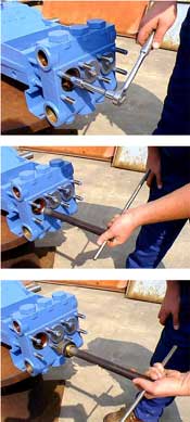
Step 1 Approximately 2 feet of clearance is required between the front of the pump fluid cylinder and any obstructions to service the piston cup seals. If there is insufficient clearance, the pump must be relocated to an area where adequate clearance exists. Step 2 To access the piston cups seals, the valve cover clamps must be removed. Standard pump models have individual clamps for each cylinder. For these pumps, remove the six (6) diagonal nuts that hold the three (3) bar clamps in place, then remove the cylinder covers. Do not remove the two (2) nuts on the opposite corners of the fluid chamber, as they will keep the fluid cylinder securely mounted on the pump during this operation. Step 3 Some pumps may be equipped with a single cover plate that secures all three (3) cylinders. For these models, all eight (8) fluid chamber nuts must be removed to facilitate removal of the cylinder covers. Step 4 Using a socket wrench with a long extension, remove the packing nut from the piston assembly. This nut secures the piston assembly to the crosshead rod. Step 5 Once the packing nut has been removed, use the FMC Technologies piston tool (A5049) to pull the piston assembly from the liner. Insert the FMC piston tool inside the cylinder until flush with the face of the slotted piston retainer nut. Twist the tool to engage and lock the tabs of the tool inside the mating slots in the retainer nut. Step 6 Pull the piston assembly free of the pump using a combination pulling and twisting motion. Step 7 Place flats on the bottom of the piston holder in a vice or clamp to secure. Using the FMC Technologies piston tool, unscrew the piston retainer nut and remove. The piston and packing washer may now be removed. Step 8 Inspect all parts for damage or unusual wear. Insure that the interior surface of the piston liner is smooth and free of cracks and grooves. New piston seals will fail prematurely if installed in liners with damaged bores. FMC Technologies strongly recommends that all 3 piston seals be replaced, not just those that show signs of leakage, whenever this type of service is performed. This will insure maximum operational time between service intervals. Step 9 Reverse the previous steps to rebuild the pump. FMC Technologies recommends that all seals or gaskets that are disturbed during service procedures be replaced. This includes the seal holder o-ring that is located on the crosshead rod directly behind the piston assembly. Step 10 Insure that all fasteners are tightened to the values specified in the Fastener Torque Requirements.
|
|