|
|
Replacing L09-HD Suction and Discharge Valves |
|
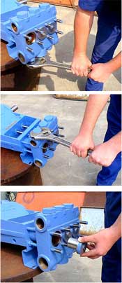
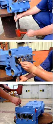
Step 1 A minimum of approximately 2 feet of clearance is required above, below, and in front of the pump fluid cylinder to allow valve service without removal of the fluid end. If sufficient clearance is not available, the fluid end must be removed as outlined in previous sections and taken to a bench for valve service. Step 2 Remove the three inlet drain plugs from the bottom of the fluid cylinder. Step 3 Remove the three discharge valve covers from the top of the fluid cylinder. Step 4 The cylinder covers must be removed to allow removal of the inlet valve assemblies. Standard pump models have individual clamps for each cylinder. For these pumps, remove the six-(6) diagonal nuts that hold the three (3) bar clamps in place, then remove the cylinder covers. Do not remove the two-(2) nuts on the opposite corners of the fluid chamber, as they will keep the fluid cylinder securely mounted on the pump during this operation. Some pumps may be equipped with a single cover plate that secures all three (3) cylinders. For these models, all eight (8) fluid chamber nuts must be removed to facilitate removal of the cylinder covers. Step 5 Use the FMC valve service tool, part number P504436, and hammer to drive the lower inlet valves from their seat and remove through the cylinder bores. Use the large diameter end of the tool and insure that it makes contact with the bottom of the valve seat, not the valve body. Step 6 Use the same procedure to remove the upper discharge valve assemblies and remove through the upper discharge valve cover opening. Step 7 FMC Technologies recommends that complete sets of new inlet and discharge valves be installed whenever valve service is required. Replacing only valve assemblies that have visible signs of wear will reduce the operating time between service intervals. FMC recommends replacing complete valve assemblies, never individual valve parts. Step 8Before new valves are installed the valve seats and valve bores in the fluid end must be clean and dry. Valve assemblies are secured using a self-locking taper and must make metal to metal contact to be effective. Failure to have clean mating surfaces can cause premature valve failure or damage the pump. Step 9 Lower the inlet valves into the mating port of the fluid cylinder, lift it slightly above the surface and drop. If the seat drops straight it will seize on the taper and cannot be pulled up by hand. Step 10 Use the small end of the FMC valve tool to drive the valve assemblies into the seats using several firm blows with a hammer or mallet. Three blows are usually sufficient, and additional or heavy blows are unnecessary. Insure that the tool is mated to the top of the valve body, not the valve cage. Contact with the valve cage may damage the valve assembly. Step 11 Use the same procedure to install the upper discharge valve assemblies. Step 12 Replace the cylinder covers, cover clamps, valve covers, and inlet drain plugs. Replace any o-rings or gaskets that have been moved during this procedure. Tighten all fasteners as indicated in the Fastener Torque Requirements section of this manual.
|
|