|
|
Servicing the L09HD Power End |
|
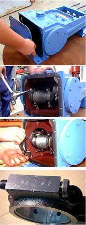
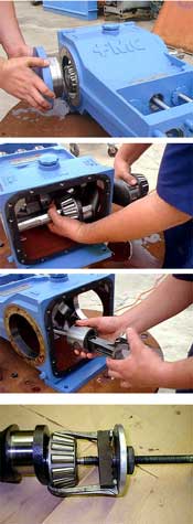
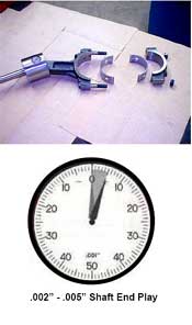
Step 1 Remove drain plug from bottom of pump and allow all oil to drain from power frame.\ Step 2 Disconnect the driver from the pump and insure that suction and discharge lines are disconnected or blocked and have no pressure applied. Removal of the fluid cylinder simplifies most power end service procedures. Step 3 Remove the 14 rear cover bolts and remove the rear cover from the pump frame. Step 4 Remove the connecting rod caps by unscrewing the two (2) nuts that hold each of the three (3) caps in place. Step 5 Connecting rods and caps are matched sets and must always be reassembled with their original mate, in the same orientation, and in the same pump cylinder. Note the numbered codes stamped on each of the connecting rod assemblies. Step 6 Push the connecting rods and crosshead assemblies as far forward into the power frame as possible to provide clearance for the crankshaft. Connecting rod bolts may be removed completely to provide additional clearance when removing the crankshaft. Step 7 Remove the left and right side bearing housings. It may be necessary to tap on the housing with a rubber mallet to free it from the pump frame. Step 8 Work crankshaft through bearing housing opening in pump frame to remove. The throws must be rotated as the crank is removed to clear the connecting rods. The crankshaft should be handled very carefully to insure the critical bearing surfaces are not scratched or damaged. Step 9 Pull connecting rod and crosshead assemblies from the pump frame. Take care to insure the are reassembled into the same bore from which they were removed. Step 10 Remove crankshaft oil seal(s) using a screwdriver or similar object and discard. Step 11 If required, remove crankshaft bearing cup and cones using an automotive type bearing puller. Step 12 Inspect all components for signs of wear or damage and replace if required. Carefully check the crankshaft bearing surfaces for pits, scratches or other signs of wear. If any of the bearings are damaged and must be replaced, FMC Technologies recommends that all bearings be replaced even though some may not show visible signs of damage. Step 13 Thoroughly clean all parts with solvent and apply a thin coat of oil before reassembly. Step 14 Tapered roller bearings cones must be heated to aid in assembly to the shaft. Always observe proper safety procedures and use heat resistant tools and gloves when handling hot parts. There are a number of recommended methods for heating bearings. Electric ovens or electrically heated oil baths may be used, but only when accompanied by proper thermostatic control. Step 15 To replace the crankshaft tapered roller bearings, first heat cones to a maximum of 300°F and slide down shaft unit it is full seated against shoulder. The hot cone may pull away from the cold shoulder unless it is held in position until it cool enough to grab the shaft. Use a feeler gauge to insure the cone is fully seated against the shoulder after parts have cooled. Step 16 Use a press to seat the new cups in the bearing housing. Never install new bearing cones in old bearing cups. Step 17 Reassemble the crosshead assemblies and connecting rods. Install new shell bearing inserts. Insure that wrist pin bushing set screws are in place if they were removed for repair or inspection of the wrist pin bushing. Step 18 Replace crosshead assemblies and push fully forward in power frame to provide maximum clearance for the crankshaft. Insure crosshead assemblies are replaced in same orientation and in same cylinder bore they were originally. Connecting rod oil cup pocket should be in the up position. Step 19 Install crankshaft in pump. Take care not to scratch bearing surfaces. Step 20 Replace bearing inserts and connecting rod caps. Insure that rod caps are assembled with mating connecting rod. Step 21 Replace shims, gaskets and bearing housings. As a start point, install same number of shims that the pump originally had prior to service. Note the gasket must be mated to the surface of the pump case, not the bearing housing. Step 22 Dial indicators and shims must be used to properly adjust the endplay of the tapered roller bearings used on the crankshaft. Improper bearing adjustment may result in excessive temperature, noise, and reduced bearing life. FMC Technologies recommends between .002”-.005” of internal axial clearance (end play) when assembled. Final adjustment must be made using a dial indicator.
Step 23 With the piston cups not installed the pump shaft should turn freely by hand. Step 24 Complete reassembly of pump. Torque all fasteners as outlined in the Fastener Torque Requirements section of this manual. |
|